I bought a couple EdgeStar AP14001HS portable air conditioners in April 2020, since I expect to spend most of the Summer at home. I'm not able to use window A/Cs here, though that would be the obvious choice for efficiency because all the hot parts remain outside.
Similar models
From looking at Internet photos, these A/Cs appear to follow the same general desgin:
- EdgeStar AP14001HS
- Whynter ARC-14S
- Whynter ARC-14SH
- Whynter ARC-141BG
- Whynter ARC-143MX
I can't say to what extent they are identical, but the stuff on this page might apply to all of them.
Air Gaps
I wanted a dual-hose air conditioner because single-hose models are thermodynamically suboptimal. Blowing hot air out the window creates negative pressure in the room, which sucks outdoor air back inside through various cracks. In theory, dual-hose models avoid this problem by cooling the condenser with outdoor air, which is then re-exhausted.
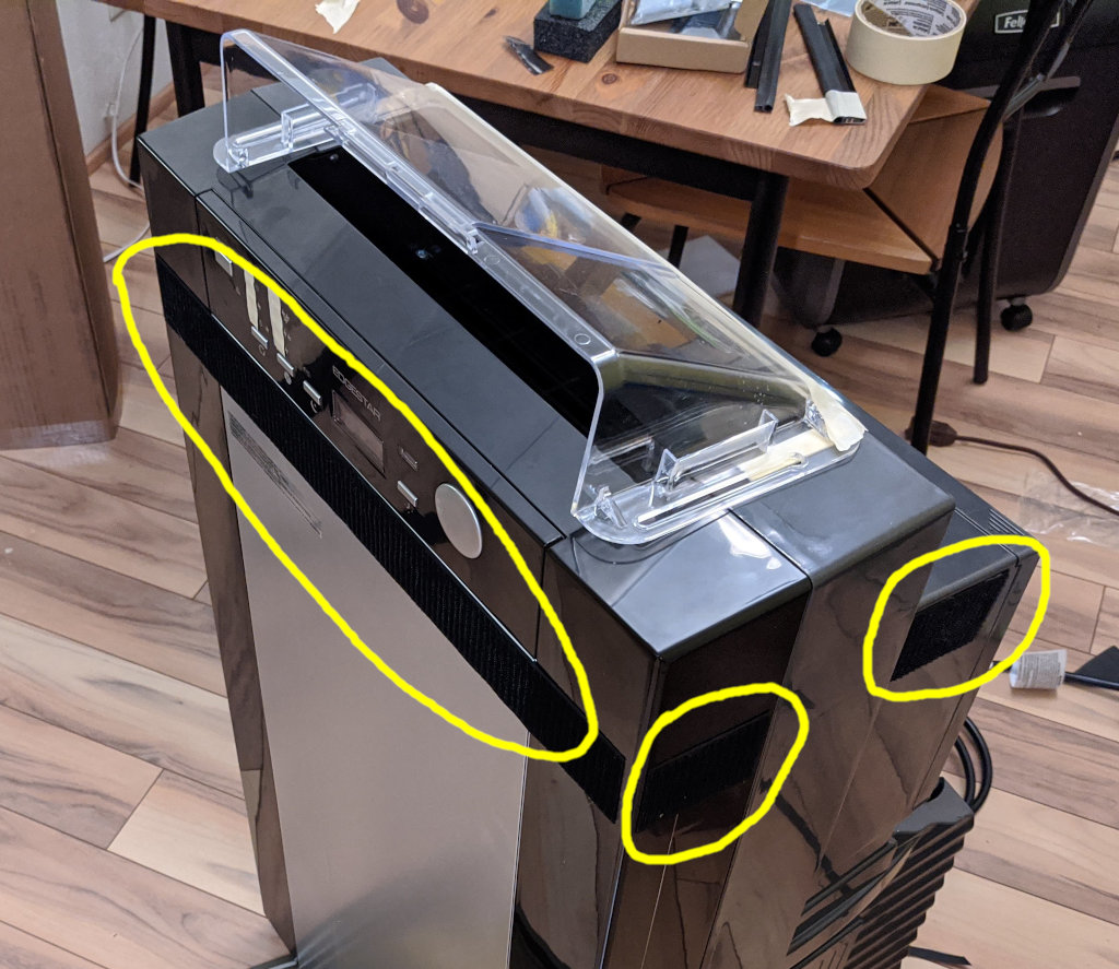
However, when I feel the intake and exhaust hoses on the AP14001HS, the volume of air moving through the intake is considerably smaller, so air must be leaking from the room into the condenser compartment, and also between the room and outside while the blower is off. There are two major locations where this happens:
- Where the bottom meets the front:
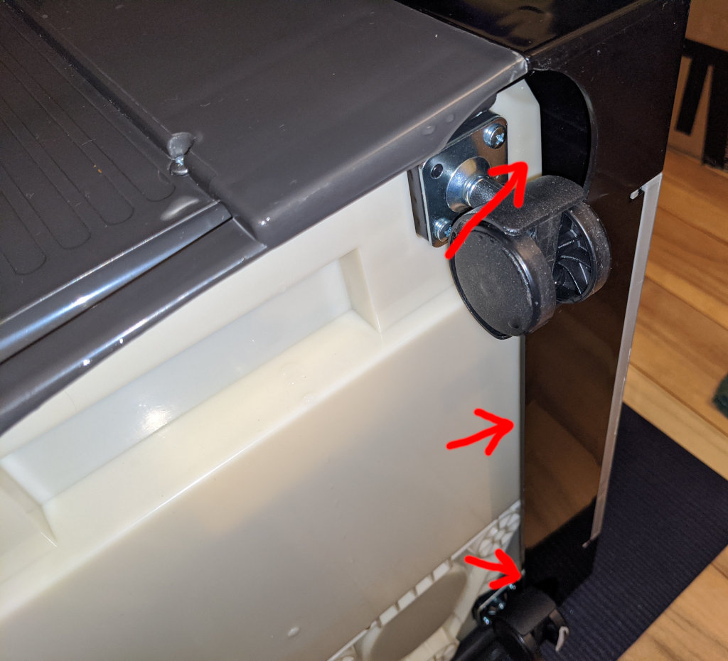
I sealed this one using tape:
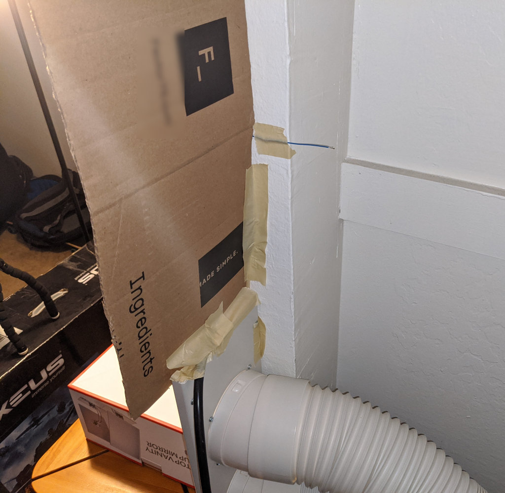
- On the back, below the air filter:
To block this one, I cut a 436mm x 98mm rectangle from a sheet of 1/16" (1.5mm) ABS plastic. A cereal box also works for prototyping purposes... in general, the material needs to be pretty thin, but rigid enough to keep itself flat.
The plastic gets pulled toward the rear while the compressor is running, and toward the front otherwise, so a piece of tape can help hold it in place.
Finally, if you decide to open the unit (a 12-inch #2 Philips screwdriver is helpful), it's possible to tape over some internal hose/wiring gaps, but I'm not sure how important these are.
Am I going to fry this thing?
These modifications are intended to make the condenser compartment run hotter, which may shorten the life of some components, but I have no idea which ones or by how much. I at least have a couple bits of evidence that this might not be a terrible idea:
- I asked EdgeStar support about sealing the bottom gap:
[Me]
I recently purchased a couple EdgeStar AP14001HS dual-hose air conditioners, and noticed that the intake hose moves quite a bit less air than the exhaust hose. It seems that the extra air is "leaking" into the condenser compartment where the bottom meets the front of the unit. See the attached photo, where I temporarily covered the gap with masking tape. Are you able to tell me whether this gap serves a necessary function? Otherwise, I would rather leave it covered, because I chose a dual-hose model to keep the inside/outside air isolated from each other.
[EdgeStar Guy]
Hello Paul,
Thank you for contacting EdgeStar support.
The area that you've taped up is considered an overflow release. You are perfectly welcome to keep that area taped up though as it shouldn't cause an issue. My engineers have informed me that it's OK to do this.
[Me]
Thank you. I had suspected that the gap was to prevent the unit from filling with water, though it seems bigger than necessary.
The AP14001HS specs say:
- Cooling Capacity (ASHRAE) 14000 BTU
- Cooling Capacity (SACC) 8600 BTU (38% lower)
According to this article, "infiltration air" is a major factor in the SACC measurement: https://support.edgestar.com/hc/en-us/articles/115005480926-What-is-SACC-Seasonally-Adjusted-Cooling-Capacity-
Have your engineers evaluated what effect sealing this gap (and other intake leaks) has on cooling efficiency?
[EdgeStar Guy]
Hello Paul,
Thank you for getting back to me.
I wasn't able to get an answer for this from my engineers about the effect on sealing the gap will have on efficiency. They did say that when the units are tested, they are tested with this gap to produce that SACC rating. There's no modifications to the units done while testing. The efficiency of the units includes the air gap.
It doesn't look like there has been factory level testing with the gap sealed, but the engineers who work on these units have performed their own tests and found covering this gap to not be an issue. They weren't able to give me additional information on the SACC though as it's not something we can test at this location.
- Someone on a plant-growing forum reported sealing a Whynter ARC-143MX tightly enough to maintain a high-CO2 atmosphere. It's not clear for what duration it actually ran, but the thread spans 4 years and the author doesn't mention a failure.
So I wouldn't say that there's no risk of damage, but at least it's been tried before.
After sealing these gaps, I could feel more air moving through the intake port, and less air coming from the exhaust when I briefly obstruct the intake.
Stand back, I'm going to try science
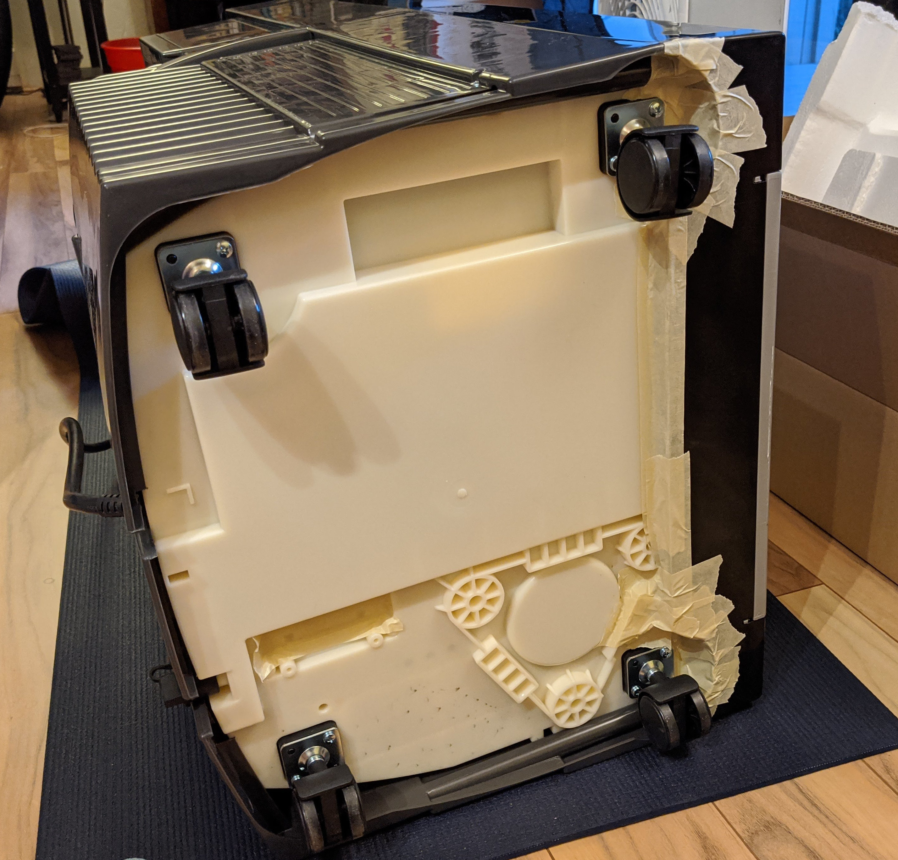
In order to test these modifications, I installed the air conditioner in a somewhat-sealed closet with a 1.5m² volume. I initialized the temperature to roughly 72°F, set the A/C to 61°F (the minimum value), and let it run for about 3 minutes until the blower shut off.
This was repeated 3 times in the factory configuration (red lines), 3 times with the gaps sealed (blue lines), and finally 2 times in "single hose mode" (black lines) with the intake sucking directly from the closet space. I logged the temperature using a phone pointed at a thermometer, running Open Camera on 10-second repeat:
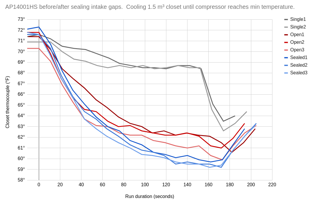
I don't think my setup is rigorous enough to calculate any absolute efficiency numbers, but clearly the sealed configuration does a better job of cooling, and single-hose mode is abysmal.
Rant
I find it disgraceful that the portable A/C companies are so clueless about efficiency that improvements can be made using basic household supplies. This reminds me of the computer PSU industry before 80 Plus, where everything is garbage and nobody knows what to buy. Why is all the innovation focused on single-hose designs?
Places like the Bay Area are full of apartments and condos that are gradually becoming unlivable as temperatures rise, so it would be nice if people could just throw money at a decent product.
It's possible that http://www.climax-air.com/ knows what they're doing, since they make (as far as I know in 2020) the only dual-hose portable with a variable-speed compressor. But I've only looked at the website, since their supply is very limited. Maybe I'll check again when the EdgeStars wear out.
Photos of the closet setup
(The second AP14001HS visible in the mirror was used to set the room temperature.)

Building-related Notes
Each unit consumes about 10.5 amps, so it's important to map out which circuit breakers feed which outlets, and avoid sharing a circuit with a high-drain appliance like a microwave or electric kettle. Ideally, they should also sit on opposite legs of the main breaker. So far, I've had no issues sharing a 15 amp circuit with a refrigerator or computer.
On a day that peaks around 95°F, two A/Cs running continuously can keep 850 sqft in the mid-70s. My IR thermometer says the ceiling is considerably warmer than the walls, so it would probably be useful to improve the attic insulation.
I plan to run these in "heat" mode during the winter, which should consume less energy than the resistive baseboard heaters, but time will tell how well that works.
One caveat to this installation is that my windows are locked/taped into position, so I can't open them at night when the air is cooler outside. It would be nice to have an automatic "ventilate" mode for this purpose. However, an A/C cooled with cool air produces even colder air, so it doesn't need to spend much time running in this state.
Simpler Hacks
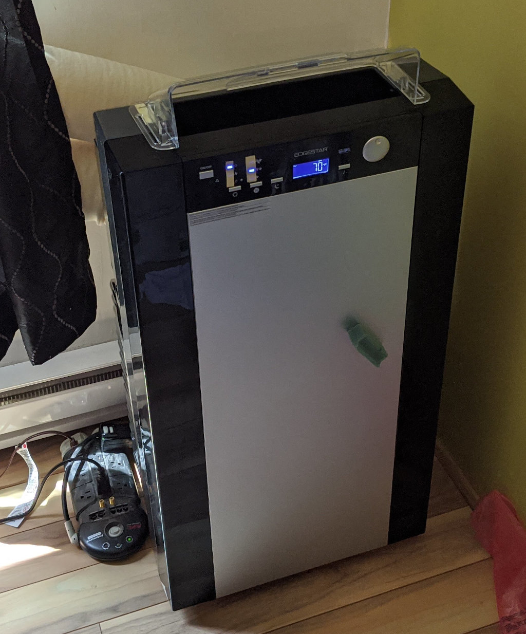
This unit blows indoor air mostly upwards. I opened the case to remove the built-in deflector, and put a Frost King HD9 in its place. This creates a roughly-horizontal air stream, and also seems slightly quieter without those extra fins in the way.
(In this photo, note that I taped over the LEDs to reduce brightness, and the chunk of foam was from an abandoned soundproofing experiment involving repositionable adhesive.)
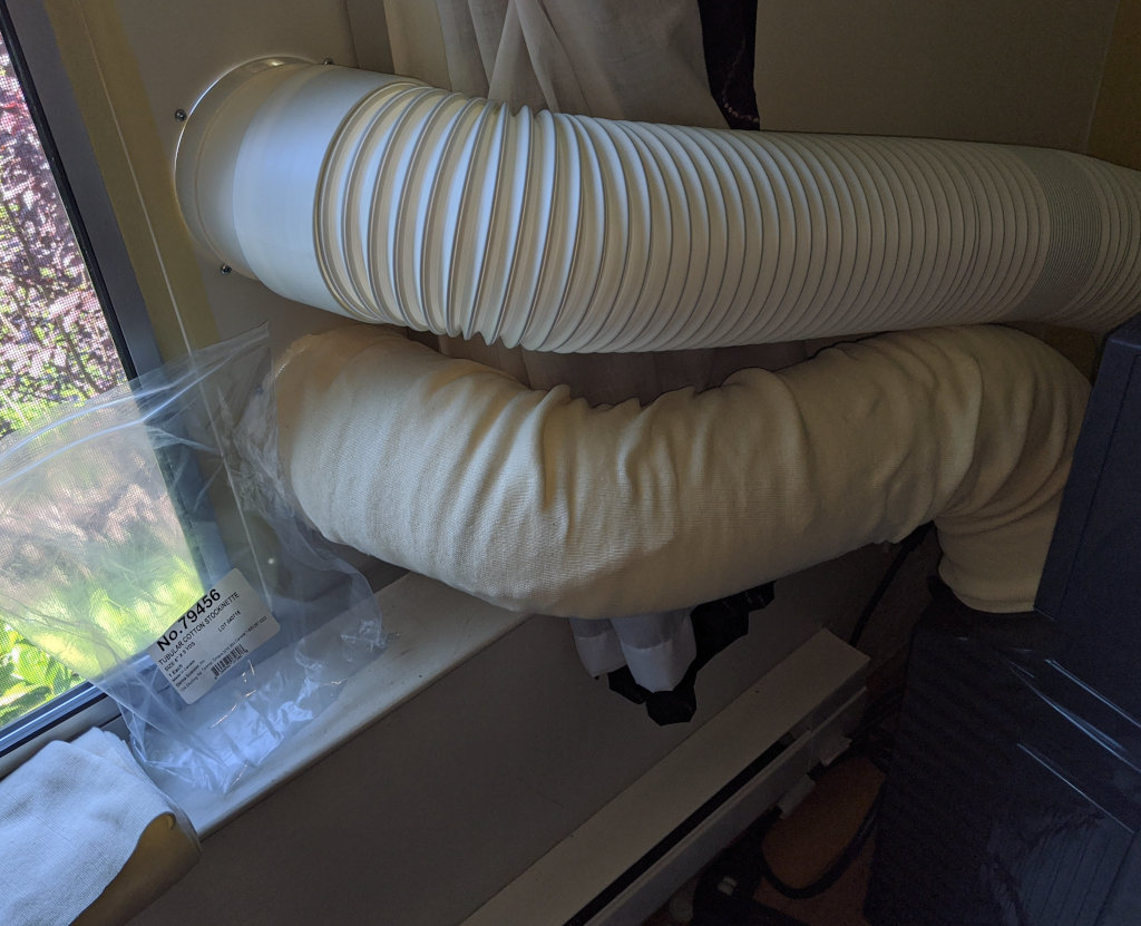
The hoses may be insulated using a 6 inch "tubular cotton stockinette bandage". After 5 minutes of runtime with 2 layers of cotton, I measured 122°F at the hose and 102°F at the cotton surface. This isn't the greatest insulating material, but it's cheap, easy, and looks reasonable enough.
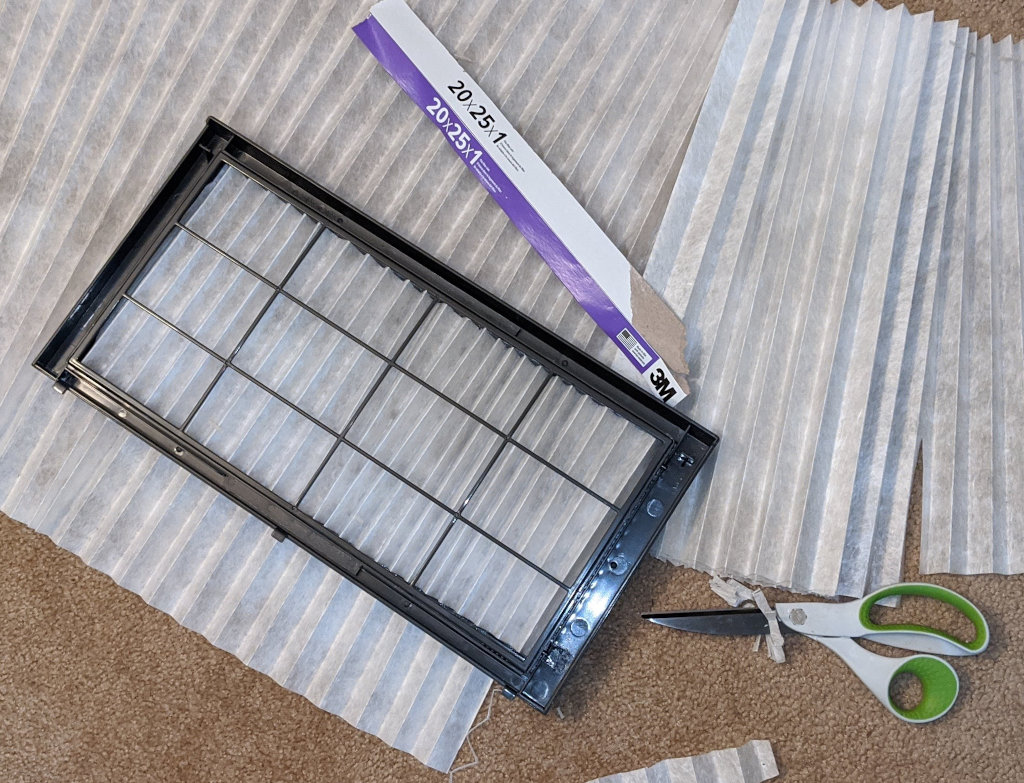
You can rip open a standard furnace air filter, and cut the zig-zag part to fit the air intake's plastic frame. Note that this will restrict airflow, so it probably makes sense to run the blower on high. I increased the density a bit after taking this photo:
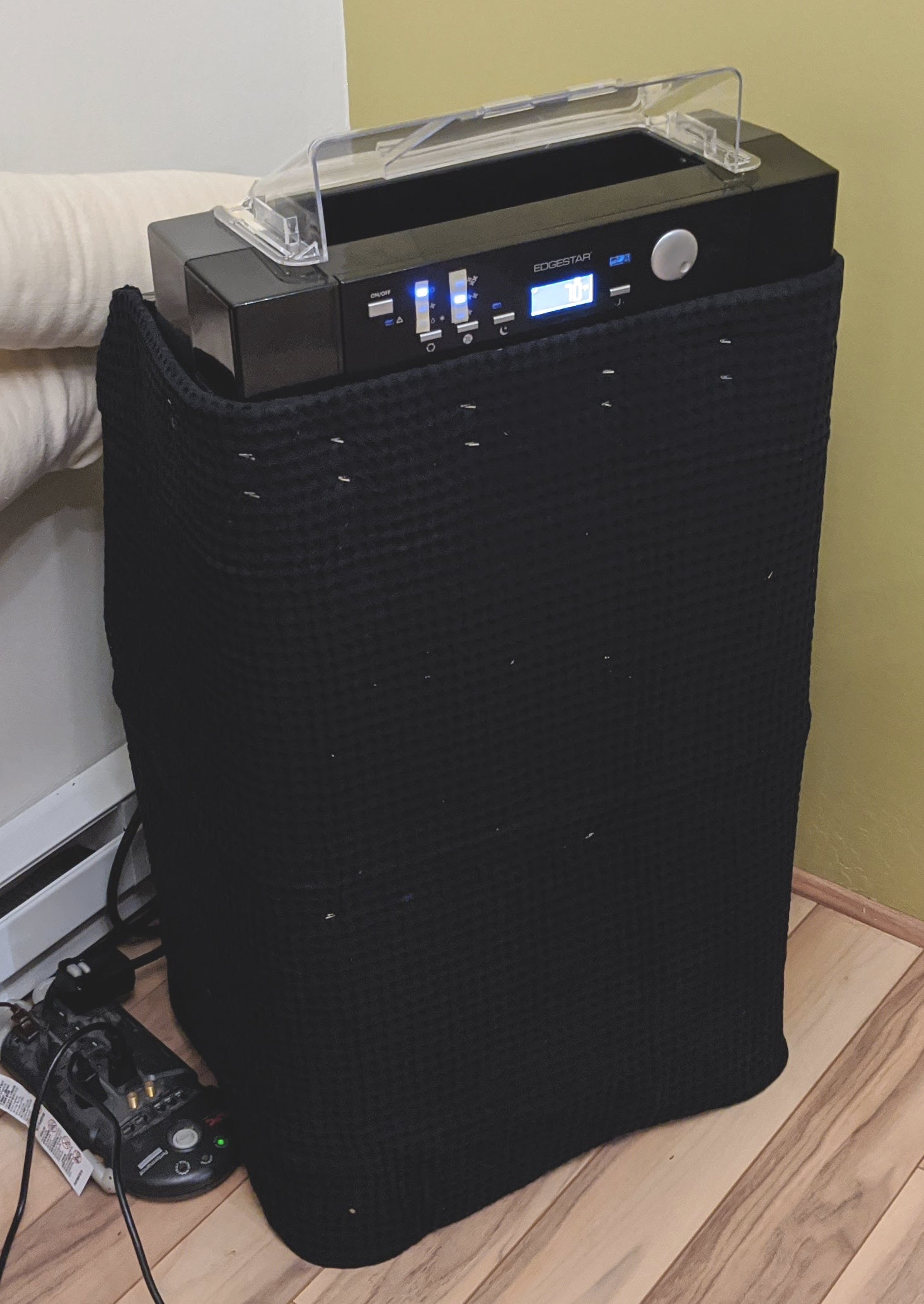
Soundproofing
To make the unit run quieter, I started by wrapping it with a blanket, held in place using tape. The hoses prevent anything from obstructing the room air intake. Here is my "A/C burrito" prototype:
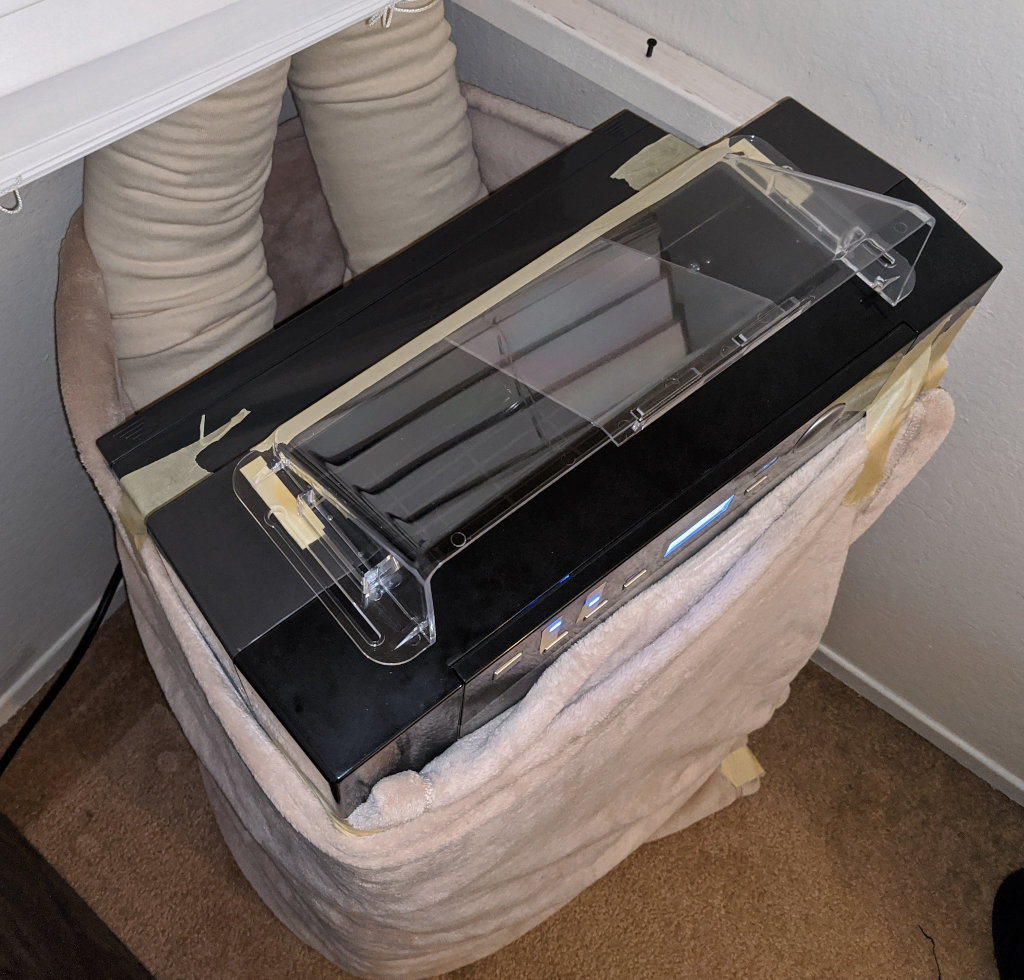
With the unit running for hours when it's 90°F outside, the hottest point under the blanket is around 94°F, so it seems to do a reasonable job of keeping itself cool.
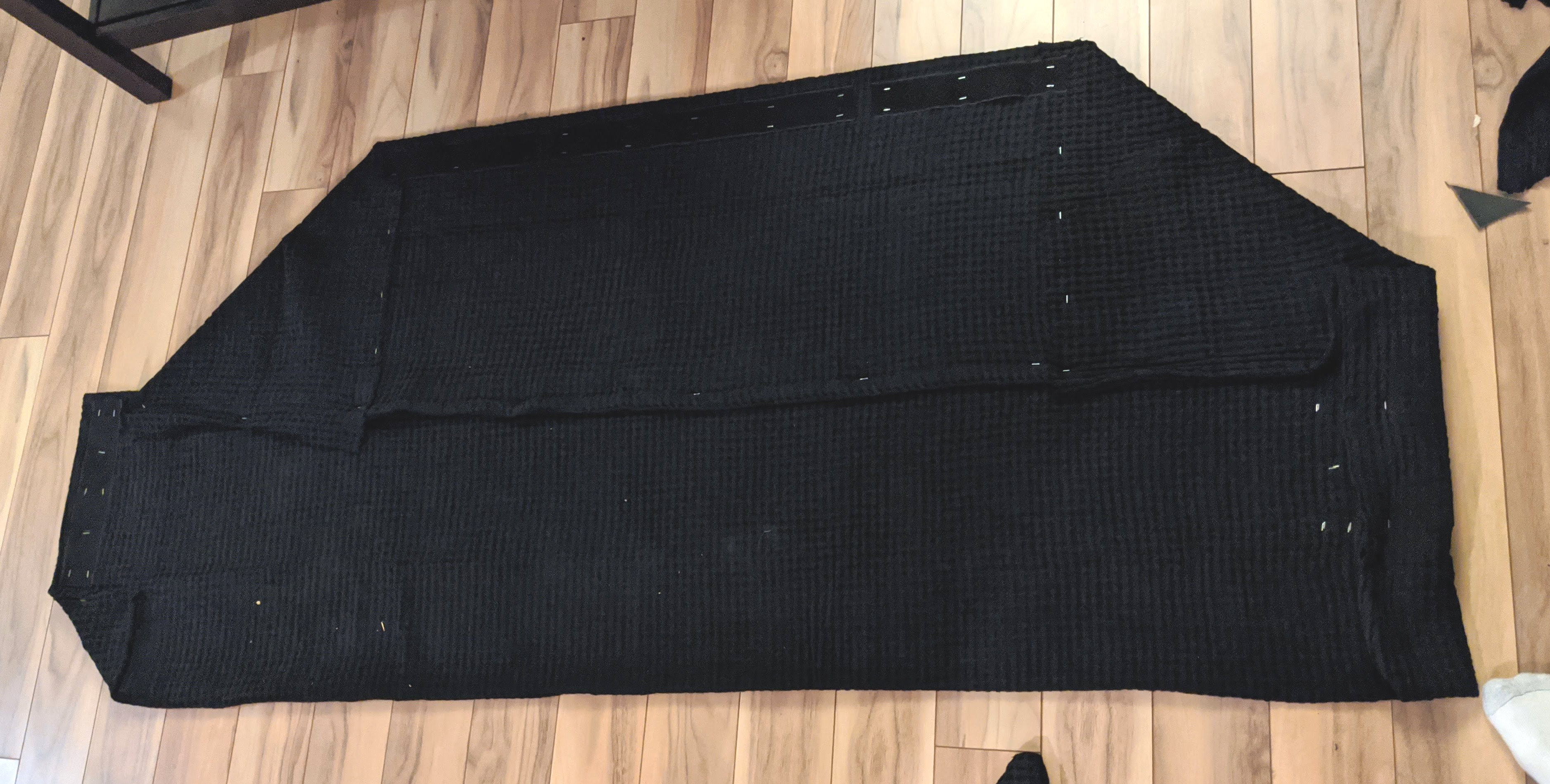
For the improved version, I used mass loaded vinyl (MLV) wrapped in cotton blanket with velcro strips, held together using staples.
The cost of materials (for two copies) was roughly:
- 4ft x 12.5ft roll of 1 pound/sqft MLV: $110
- Two twin-size (66 x 90 inch) cotton blankets: $50
- A few yards of 2 inch velcro: $10
- Staples with 9/16 inch legs (Bostitch BTHT73533): $4
These are the dimensions I used:
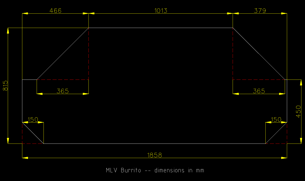
I cut the MLV to size using a tape measure, square, pencil, and scissors. Removing the bottom corners leaves room for the power cord. The wings have different lengths because the power cord is off-center.
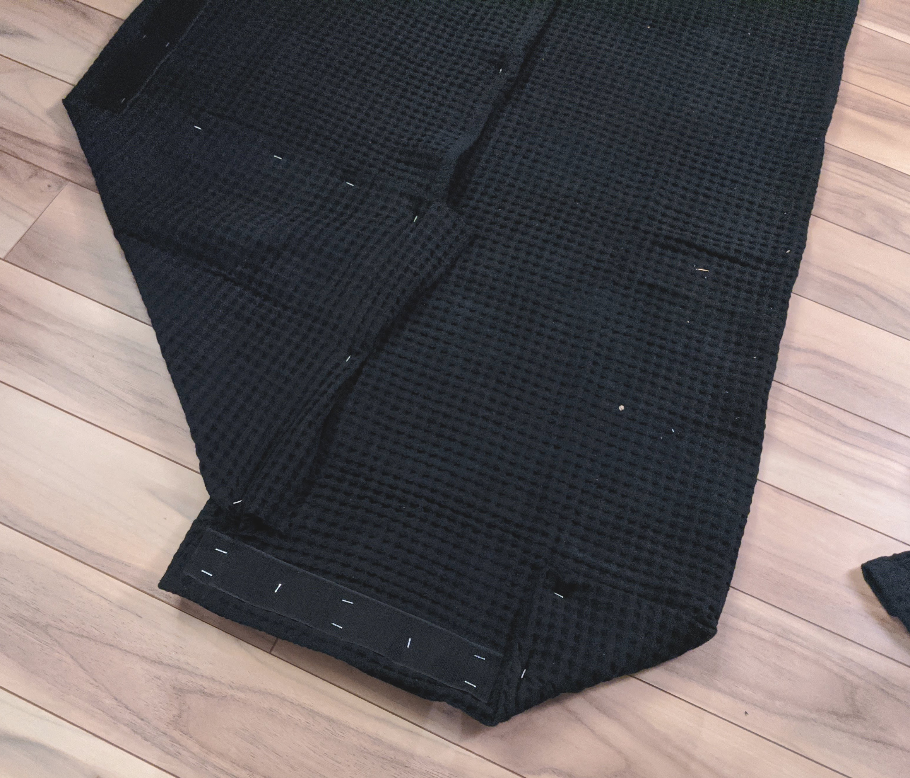
There are velcro strips along the top (with opposing velcro hot-glued to the A/C), and on the back so the burrito can attach to itself.
Photos of the MLV burrito:


All in all, MLV does reduce noise from the compressor, but there's still plenty of blower noise. I'm not sure to what extent the cotton wrap helps to reduce reflected sound, but at least it looks nicer than raw vinyl.
Pushing and bending hundreds of staples was quite a lot of work. I think I would recommend that a sane person stop with the initial "folded blanket and tape" solution, since it just takes a few minutes, and MLV isn't tremendously better.
Network Control
I connected an ESP32 microcontroller to the "compressor relay stage 1" (Y1) and "heat pump changeover valve" (O) outputs of a Nest thermostat, with "auxiliary heat" driving a relay for my baseboard heaters. (I've tested that the Nest can individually turn everything on, but time will tell how it juggles two kinds of heat in the winter.)
Each 24VAC relay output drives the input pins of an SFH620AGB optocoupler through a 10K resistor (24V / 10kohm will push a few mA through the optocoupler LEDs). The optocoupler is compatible with GPIO in INPUT_PULLUP mode, using a bit of software to clean up the signal. I got the idea from this StackExchange post, though 24VAC is less scary than 120-240VAC.
When I connect a 10K resistor between (e.g.) Y1<->C on My Nest 3rd Generation, it has no trouble detecting that a device is present, but I've heard reports that the Nest E needs a heavier load. Adding a 1K resistor (rated for at least 1 watt) in parallel with the Y1<->C connection should be sufficient.
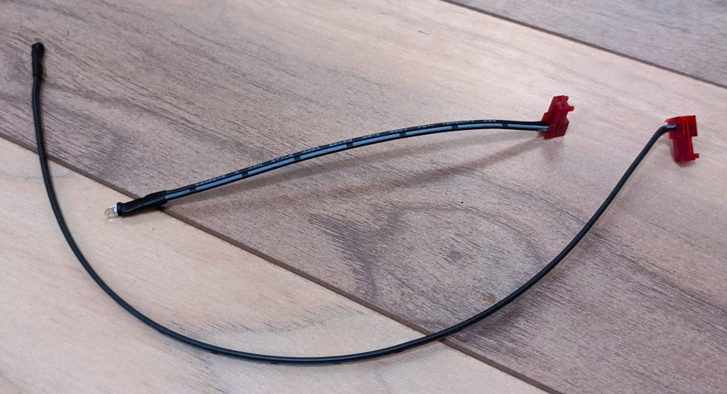
On the air conditioner side, I'm driving a generic IR LED through a 150 ohm resistor, using the sendRaw() function from IRremoteESP8266.
I cut a ballpoint pen in half, painted it black, and placed it over the mode status LEDs, with an INL-3APD80 photodiode to detect brightness changes when cycling through modes. The photodiode seems to work best in photovoltaic mode, with anode connected to an ADC input, and cathode connected to GND. I do a read every 50 microseconds, and average across 1000ms (20000 samples) to get a clean signal. Adding a capacitor in parallel with the photodiode reduces the stabilization time; 10nF seems like a good balance between noise and responsiveness, reducing the read time to 100-200ms.
The point of connecting portable A/Cs to a Nest is:
- The usual "smart" stuff that Nest provides
- Longer compressor cycle times because the thermostat and A/Cs are physically separated
- When heating/cooling is not needed, the A/C's fans can power down, to reduce noise and save 60-70 watts
I captured the remote codes using LIRC's mode2, which provides mark/space times in microseconds, compatible with the sendRaw() function mentioned previously.
Reverse engineered IR protocol: all marks are the same length, with data encoded in the spaces. There appear to be 32 bits per packet, organized as [id, ~id, code, ~code]. I tried sending all 256 codes, hoping to find undocumented features like "set power to X" or "set mode to X", but alas, they were all just duplicates of the standard 6 buttons, so understanding the protocol is pretty useless.
Here are the simplified IR codes in irrp.py JSON format (I was initially playing with pigpio on a Raspberry Pi.)
This algorithm allows the ESP32 to discover the state of the A/C from a blind start:
- Sample the photodiode brightness
- Send POWER
- If the brightness increased, we just turned something on, so send POWER again
- Now we know the unit is off
- Send MODE 4 times, capturing the brightness after each event
- Label the brightest mode COOL (because this LED is closest to the photodiode)
- Label the other modes by their order relative to COOL
It's possible to synchronize the fan speed by briefly running DEHUMIDIFY (which forces the fan to LOW), but I decided not to do this, and just let the user choose the fan speed.
I encountered the following AP14001HS-specific bugs:
- It is impossible to reliably switch modes while the power is ON, because switching from (e.g.) COOL->DEHUMIDIFY->FAN will sometimes apply the intermediate mode (DEHUMIDFY), even when blasting IR as fast as possible. Thus, I had to idle the compressor by sending TEMP UP instead of switching to FAN.
- With the power initially OFF, sending MODE-MODE-POWER will sometimes start the wrong mode, or do strange things like run the compressor without the exhaust blower. The solution is to wait 1000ms between the last MODE, and POWER.
- Cycling through modes while OFF will "corrupt" the stored temperature, lowering it by 0-2 degrees. This only happens in fahrenheit mode, so I suspect that there's a lossy F->C->F conversion happening somewhere.
- A power loss while the A/C is running triggers a reboot into fahrenheit mode, and there is no way to enter celsius mode via IR commands; this is quite annoying.
- When sending IR commands back to back, you must leave a gap of at least 1200us to avoid lost events. In retrospect, this isn't really a bug, since it's similar to sending a "1" bit.
It's possible to set a specific temperature by sending enough DOWN commands to reach the minimum value, followed by enough UP commands to reach the desired temperature. In theory, the controller could always use 16C for cooling and 32C for idle, but I prefer 18C-27C, because it only needs 9 clicks (shorter beep), and the user can manually raise the cooling point to prevent a smaller room from getting unreasonably cold. Manual adjustment is only possible in celsius mode due to the temperature corruption bug, so it's unfortunate that unplugging the power reverts to fahrenheit. My best idea was to initialize cooling mode by sending enough UP commands to max out the fahrenheit range, and likewise for DOWN commands in heating mode. All adjustments after this point assume celsius, so the temperature will never get cold enough to cool, or hot enough to heat, until the user restores celsius mode and reboots the ESP32. In other words, it seems better to never work than sort of work.
Controller photos
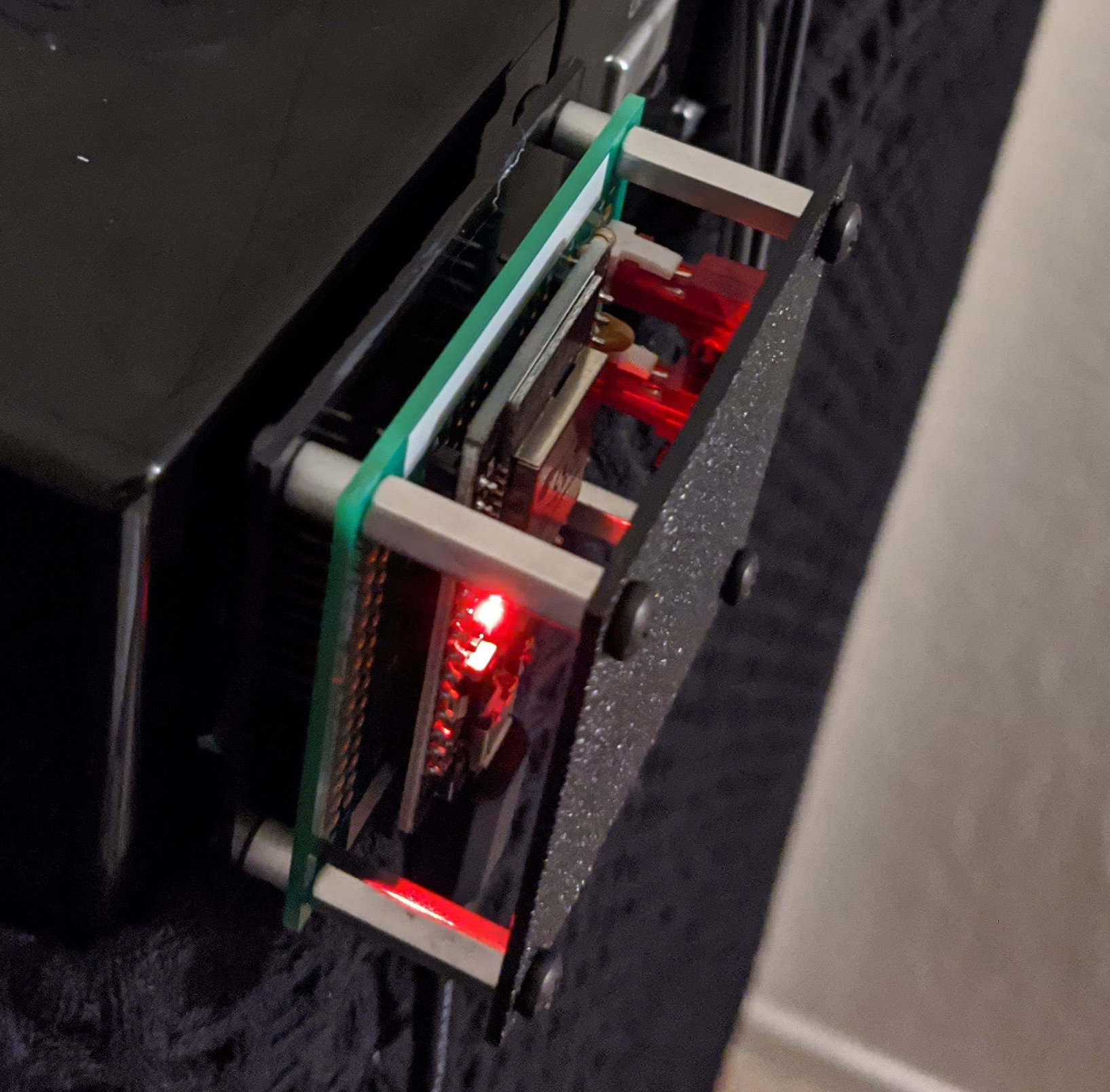
I couldn't find an enclosure with the right dimensions, so I cut out some ABS rectangles with a utility knife, attached using 5mm and 12mm M3 screws, with 18mm standoffs and 5mm spacers.

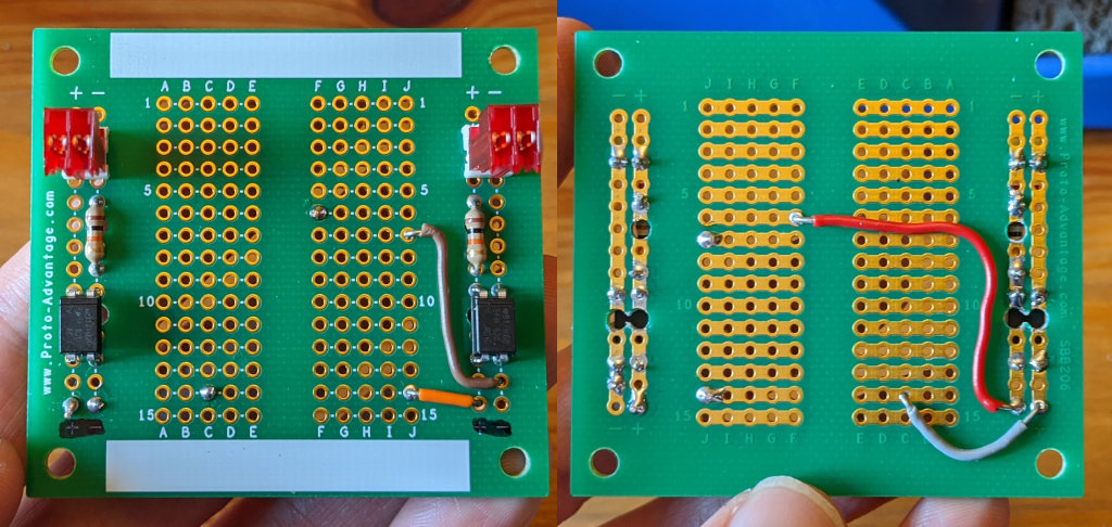
The circuit board is a Proto Advantage SBB206. It fits the 15-row ESP32 dev board exactly, though it'd be nice if the dev board were 1 pin narrower. Drilling holes in the power rails lets them hold general-purpose components.
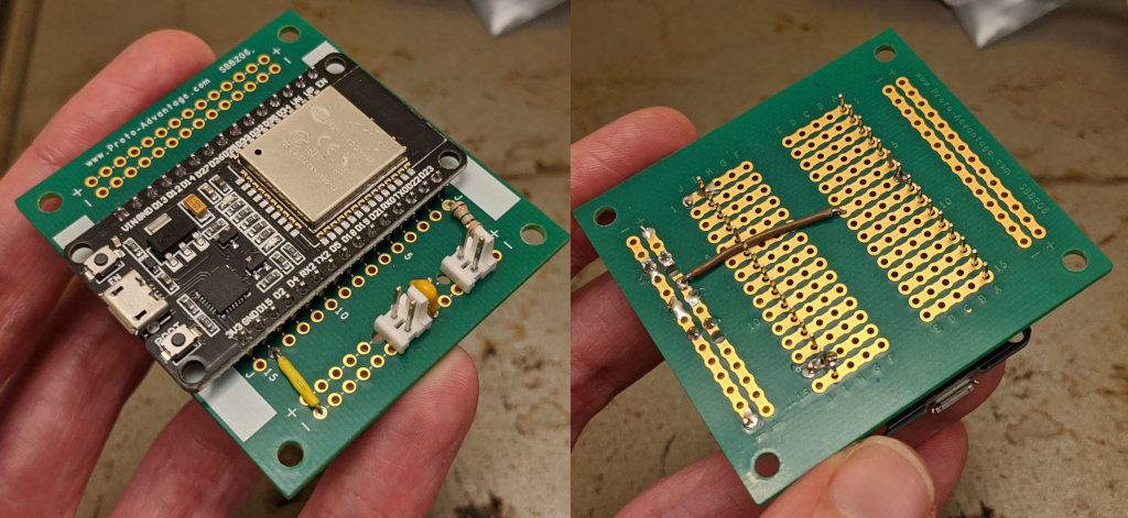
The photodiode and IR LED dongles are attached to 22AWG MTA-100 connectors. I used a small screwdriver in lieu of the $35 Insertion Tool.
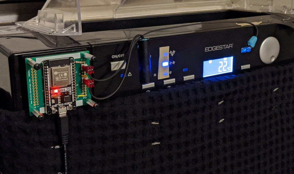
Here is the controller stuck to the AP14001HS:
Thermostat/Relay photos
24VAC relay module, with 10K resistors and optocouplers (Note: for compatibility, it may be useful to parallel each connector with a 1K 1W resistor):
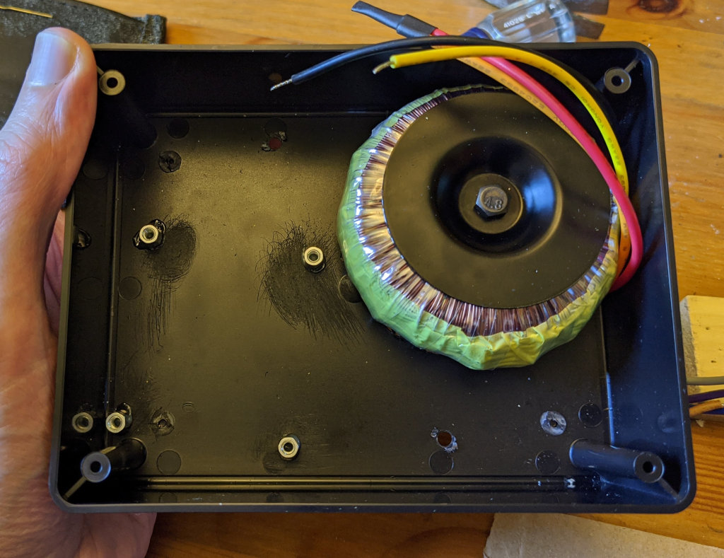
Bud Industries CU-387 enclosure with Vigortronix VTX-146-030-212. The transformer converts 120VAC (parallel windings) to roughly 30VAC, or 208VAC (series windings) to roughly 25VAC. I roughened the plastic with sandpaper and epoxied 6mm M3 standoffs in place; hopefully that'll hold well enough.
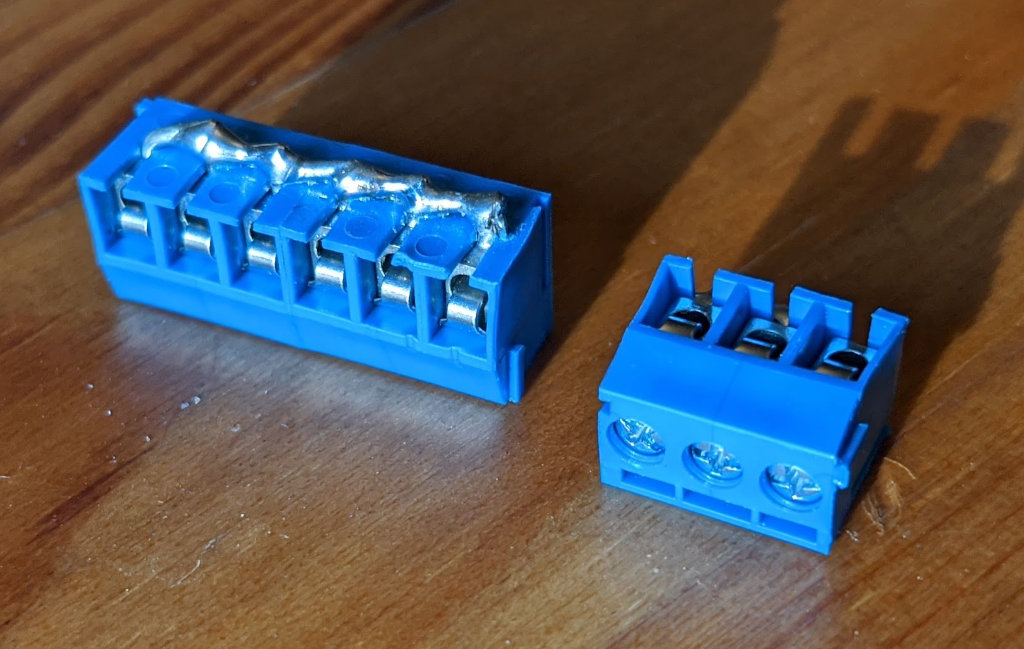
To attach the 24VAC wires, I took some 3.5mm screw terminal blocks (TE 1776275-6), bent the pins sideways, and soldered them to form a bus. The exposed metal was wrapped with electrical tape.
Here is the thermostat enclosure with everything mounted, including a 24VAC to 5VDC power supply at the bottom. I stuck with MicroUSB, so I can't forget to unplug the power before reprogramming it.

The junction box originally held a 208VAC thermostat for baseboard heat. I added a Schneider Electric 92S7A22D-24 relay, which the Nest identifies as "aux heat" via the white wire. Actually, the relay and transformer are the only components needed to use the Nest as a line-voltage thermostat.

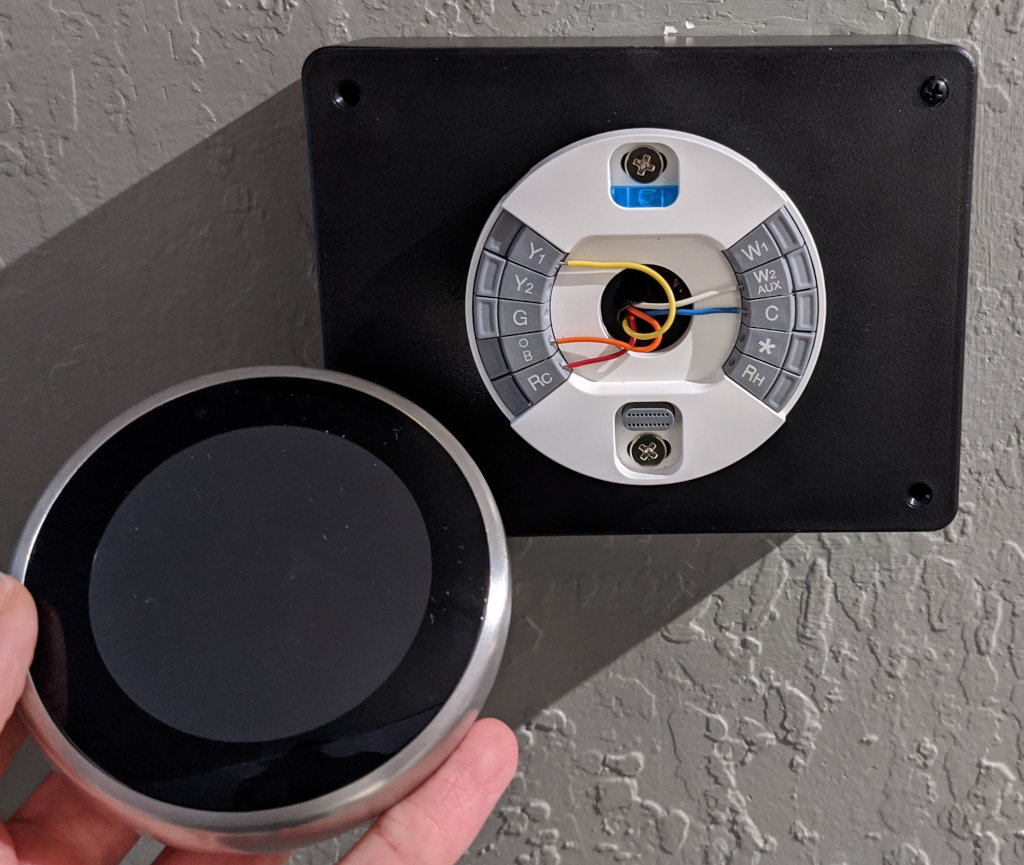
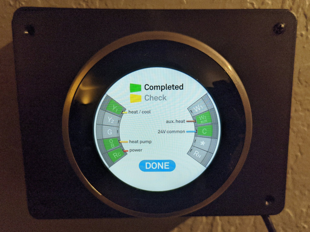
Here is the Nest in various stages of attachment:

Source code
https://github.com/pmarks-net/ac/
Videos
- Monitoring light levels (2020-06-07): https://www.youtube.com/watch?v=C5tmRAij6e0
- Detecting 24VAC (2020-06-17): https://www.youtube.com/watch?v=C4kNbceWMxM
- System Demo (2020-07-12): https://www.youtube.com/watch?v=_ziA3l_pd60